Ciruits and Sensors
Introduction
This page provides a documentation of my journey in the first week of the second fortnight. The week's reflection highlights a practical introduction to circuitry fundamentals, the installation and use of Adafruit Circuit Playground Express (CPE), the lessons learned from my failures and struggles with the components, and the incorporation of these lesson in the subsequent activities. Prior to this fortnight, I had only worked on electric circuits once in 2014 during my first degree, and I had vague memory of what computer electronics was about but was excited to "get my hands dirty". At the end of the sessions, I built electronic systems, the hands-on experience made me have an overview of the essential components that typically makes up these systems
Learning Resources
The skills session was preceded with getting familiar with the concept of circuitry, electronics and sensors from the outlined rich resources:- A refresher class on Electric charge, Current, Resistance, Voltage, Power and Circuit design fundamentals
- Installing Adafruit Windows Driver following the instructions here
- Installing CPE CircuitPython 5.3.0 here
- Updating the CPE Bootloader following the instructions here
- Installing Mu Editor from here
- Reading the CPE documentation and getting started tutorial to get familiar with the CPE pins and onboard sensors
- Reading the TMP36 Tempreture documentation
Key Skills and Components
- Jumper wires
- Resistors
- Light Emitting Diodes (LEDs)
- Battery
- Breadboard
- Adafruit Circuit Playground Express board
- USB cord
- Adafruit CPE Bootloader
- LM35 Sensor
- Python
- Code Editor: Mu Code
Activities
Lighting Up an LED
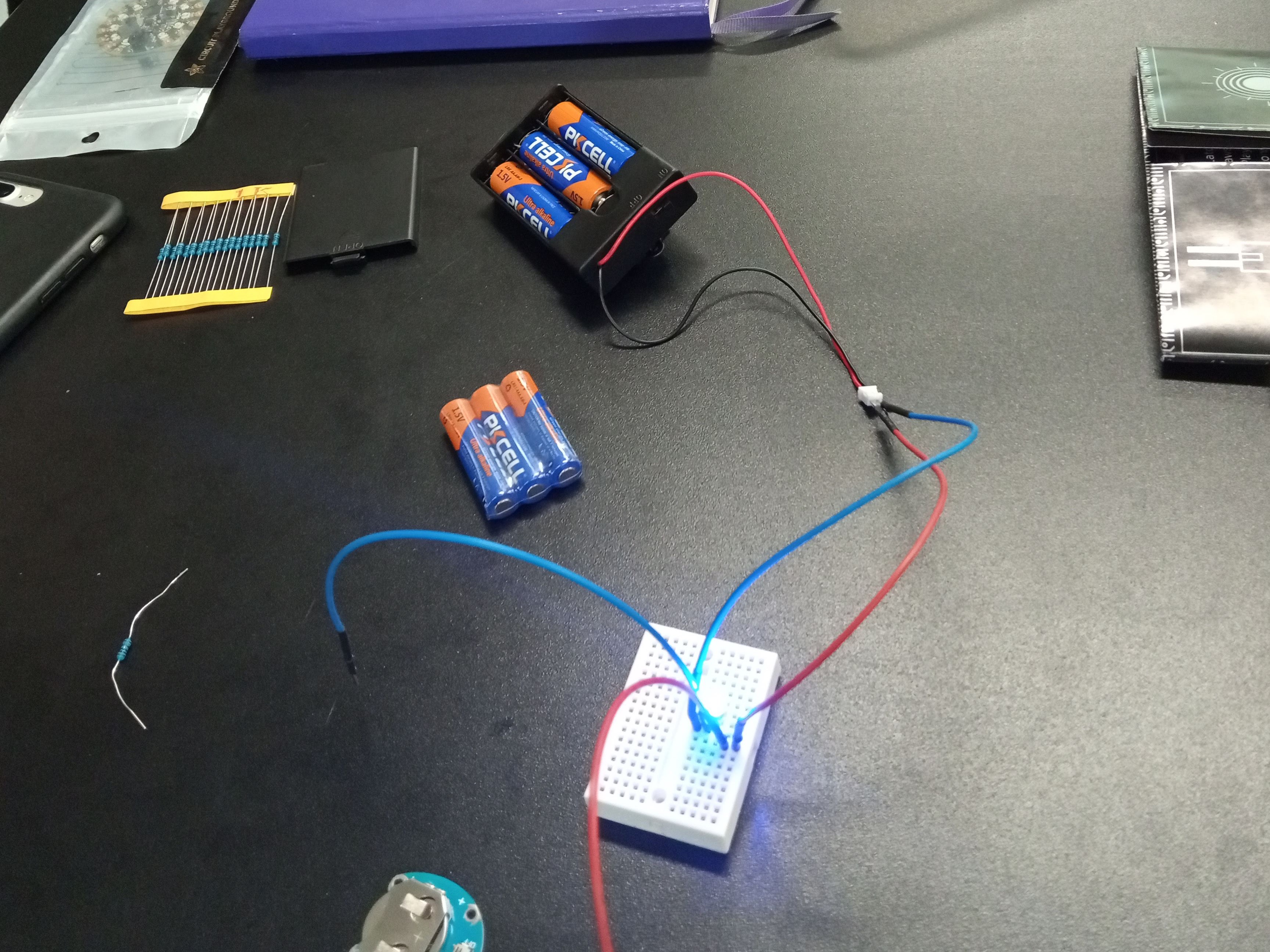
For this activity, we started with trying to light up an LED by connecting it to a battery through a breadboard. First we had know which LED leg to connect to power and which to connect to ground, that is, which is the cathode (long leg) and which is the anode (short leg). After successfully connecting the LED to power, we tried to see how much current the LED can take without burning out. Given that LEDs typically need 3.3V-5V power, we connected a 4.5V and a 3V battery to the LED, but the LED didn't burn out. It turned out we connected the batteries wrongly. Our connection was in parallel, to burn out the LED, I has to be in series; it became a practical lesson on series versus parallel circuits as shown in the images below.
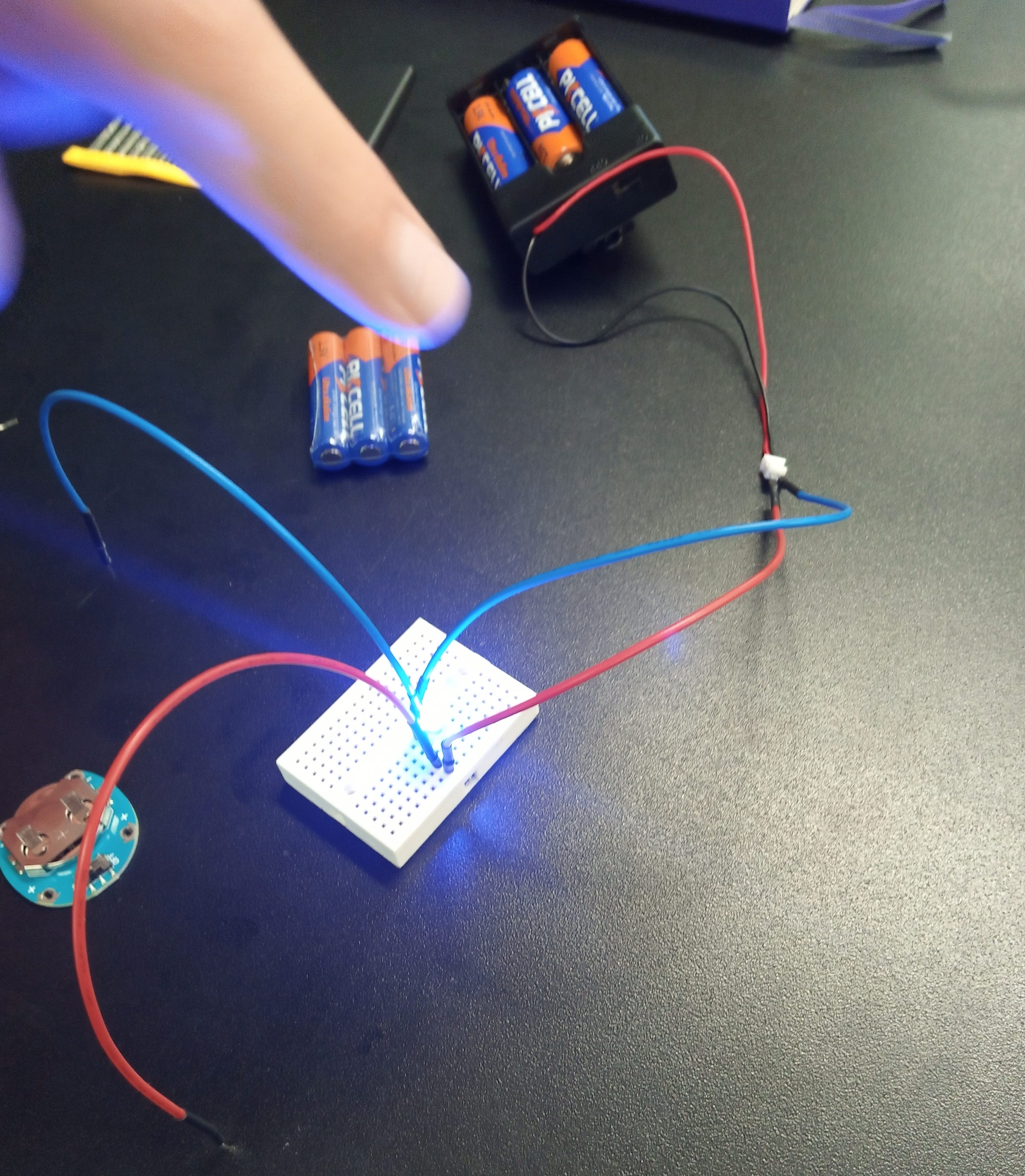
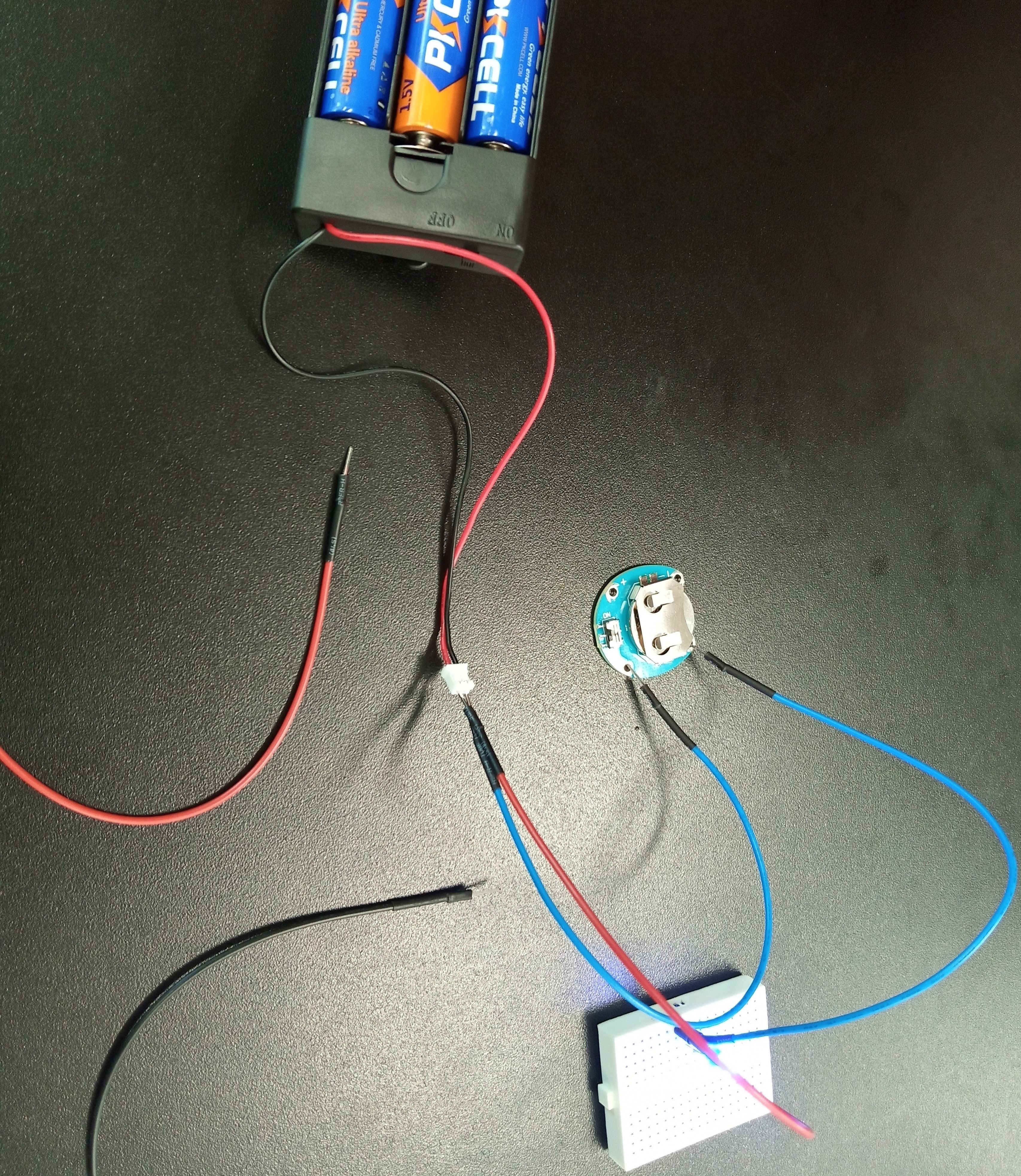
Afterward, we connected a 1k resistor to the circuit to reduce the current going to the LED, to avoid the LED getting "fried" due to power surge.
Play with Ciruit Playground Express Board Sensors
With the lesson learned from experimenting with the LED, the functions and purposes of the Ground, the Vout and the 3.3V pads on the CPE board became clearer. Following the CPE guide, I was able to:
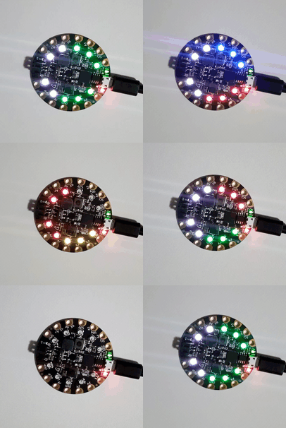
- Blink the LEDs on the CPE
- Use the CPE onboard switch and buttons to control the board's operations
- Use the onboard accelerometer to detect movements, taps, shakes and use the state of the acceleromemter to control my program execution
- Detect my room temperature, light brightness level, and noise level using the onboard temperature, light, and sound sensors. I also used the levels to control the CPE's LEDs
- Programme the onboard NeoPixel LEDs to display the colors of various country's national flags
Comparing CPE Board Vs. LM35 Tempreture Sensors
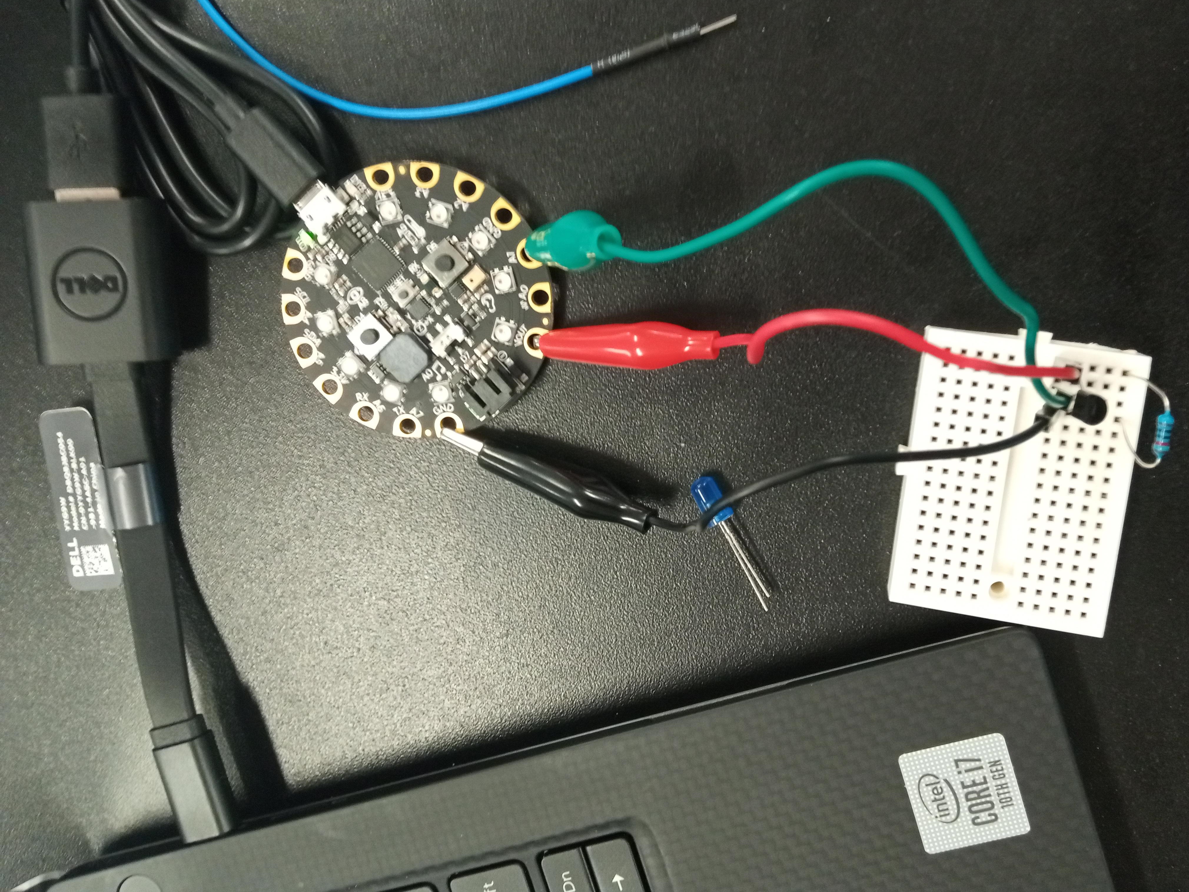
This was an additional group exercise to print the temperature of our environment using the CPE onboard tempeature sensor and the LM35 temperature sensor. We read the TMP36 (similar to LM35) sensor's documentation to learn about the sensor, its architecture and pins, power requirement, and how it measures temperature.
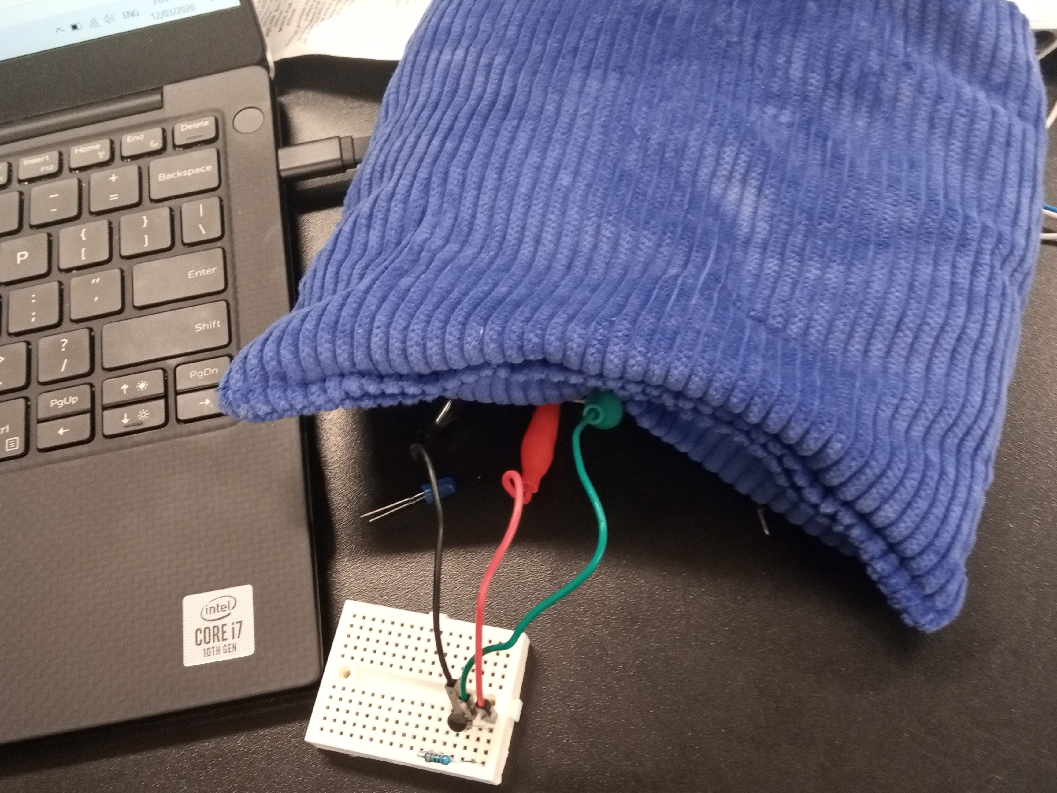
When the temperature data from both sensors got printed out, we noticed variations in the printed data which we learned was due to the in-built resistor on the CPE - the resistance value of the CPE affects the measured temperature. We also attempted to see if we get the same measurement from the LM35 by adding a resistor to its circuit. As seen in the images below, we attempted to change the measured tempeature by placing an ice pack on the sensors, they measured lower temperature some seconds after.
Challenges and Solutions
-
Connecting components to the circuit accordingly: since it was my first time figuring out the right amount of power to be connected to a circuits connection, it was quite challenging. I had to figure out the current limitations of the components, decide if the connection should be in series or parallel, determine when to use resistors, and correctly connect the power and ground to the right pins.
Solution: I learned that the best way to go about this is to read the specifications, requirements and documentation (if available) of every component on a circuit. Also, I have to ensure I am familiar with the components pins or pads and their functions before connecting them to the circuit.
-
Troubleshooting hardware/software interface: According to the instructions, once I plug in the CPE board using a USB data cable after I had successfully installed CircuitPython on my computer, I will see the CIRCUITPY drive folder. However, having followed the installation instructions carefully, I still couldn't see the drive folder whenever I plugged in the CPE. I spent days trying to figure out what went wrong or what was missing.
Solution: I reached out to Zena (one of the course instructors) and we tried to figure out what was wrong, it turned out I was supposed to press the CPE's reset button twice for it successfully mount on my computer and for the drive folder to be visible.
-
Logging temperature data and timestamp in the right format: one of our tasks involved measuring and logging to a file, real-time temperature data and their timestamp from the CPE temperature sensor. After many futile attempts, I was able to log the data to file by carefully following this guide. However, the timestamp was not being logged in the desired format and Python3 time and date functions were not recognized by the CPE.
Solution:After an extensive research, I was able bypass this constraint after reading the CPE Python custom time module documentation. Being familiar with the CPE in-built functions and their return value made me to able to determine what functions I could use and manipulate to record the timestamp in the desired format.
Takeaway Lessons
- When setting up or building electric circuits, every detail counts! I was stuck for days because I omitted the fact that I was supposed to press the CPE's reset button twice in the instructions
- After assembling the components, it is important to test the circuit to ensure that every component is still functional and not faulty, and the circuit connection was done correctly.
- It's also helpful to read the components' documentation and find out their limitations - saves time and effort
- The tools used for collecting "raw" data may affect the accuracy and integrity of the collected data. It is important to be familiar with these tools and the limitations or inconsistencies they bring
- Most importantly, I should always communicate and seek help when needed; I should help others whenever I can too.
Achievement
At the end of the activities, I learned how to:- Connect components to circuits correctly and troubleshoot them.
- Program CPE in circuit python.
- Manipulate the CPE program execution based on the data from the sensors, buttons and switch.
- Measure temperature data using the CPE and the LM35 temperature sensors